Micropolis 1664-Models
CONFIGURATION INFORMATION
Configuration and Jumper Options
The drive's circuit board will look like one of these drawings. Refer to the drawing that looks most like your board.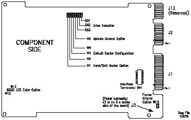
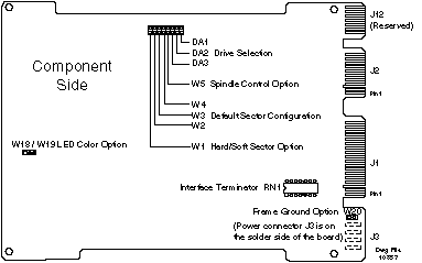
        Drive	  Select Jumpers
       Address	DA3	DA2	DA1

  	1	out	out	in
  	2	out	in	out
  	3	out	in	in
  	4	in	out	out
  	5	in	out	in
  	6	in	in	out
	7 	in	in	in

	"Drive Address 0" (no jumper at DA1, DA2, or DA3)
	 is a "deselect" (i.e., no drive selected).
For many multiple drive installation, each drive must have a unique address. An exception is that for every drive in a PC/AT installation, verify that the only Drive Address jumper is at DA2; move the jumper if necessary (the special twisted interface cable that is generally used takes care of adding a unique address to each drive). PC/AT controllers can typically support a maximum of two drives. Interface Termination The Interface Terminator factory installed at RN1 provides proper termination for the interfacelines. When daisy-chaining multiple drives, leave the terminator installed only in the last physical drive on the daisy-chain cable; remove the terminator from each of the other drives. In most PC/AT applications, the C: drive is actually at the end of the cable and should retain the terminator
Spindle Control W5 controls the spindle option. If W5 is installed, the drive waits for a Start Spindle command (after power is applied) to start the spindle motor. If W5 is not installed (the factory default configuration), the drive automatically starts the spindle motor at power-on. W5 is not installed for PC/AT applications.
Sectoring W1 selects the sectoring mode. If W1 is installed, the drive operates in the soft-sectored mode. If W1 is not installed (the factory default configuration), the drive operates in the the hard-sectored mode. W1 is not installed for PC/AT applications. The number of bytes per sector may be specified using the Set Bytes Per Sector command or by selecting a default sector configuration with jumpers W2, W3, and W4 as follows:
      Jumpers		Sectors			Bytes/Sector
  W4	W3	W2			Formatted	Unformatted
  out	out	out	   53		   512		   588 *
  out	out	in	   54		   512		   578
  out	in	out	   28		  1024		  1116
  out	in	in	   14		  2048		  2232
  in	out	out	    7		  4096		  4464
  in	out	in  (Reserved - Do Not Use)
  in	in	out	   97		   256		   322
  in	in	in	    1		31,248		31,248

  * This is the default (factory installed) configuration,
    and is recommended for PC/AT applications.
LED Color Option A jumper at W12 or W13 (W18 or W19 on the lower-shown board) selects the color of the LED.
    W12 (W18)   W13 (W19)
    Yes   	No    		The red LED is selected
    No    	Yes   		The green LED is selected. (Default)
Frame Ground Option A jumper at W14 (W20 on the lower-shown board) selects the frame ground option.
    Jumper	Frame ground connected to logic ground.
    No Jumper	Frame ground not connected to logic ground.
		  (This is the default configuration and should be
		  used for PC/AT applications.)