ELECTRICAL INTERFACE
1664 ELECTRICAL INTERFACE
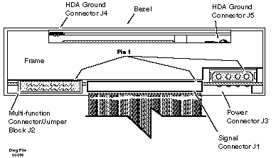
Electrical interface between the Micropolis 1664 drive and the host system is accomplished via connectors as shown in the figure below.

Control Signal Connector J1 is a 34-pin board-edge connector. The signals on this connector control the drive and transfer drive status to the host controller.
Data Transfer Connector J2 is a 20-pin board-edge connector. The signals on this connector contain read or write data.
DC Power Connector J3 is a 4-pin connector used to supply +5V and +12V to the drive.
Ground Connectors J4 and J5 are 3/16-inch spade lugs located on the HDA and frame, respectively, and are used for grounding purposes. System characteristics determine proper ground connection.