
Micropolis 1335
Hard Disk Drive
Overview
| Model | Capacity | Size | Height | Interface | Bus Type |
|---|---|---|---|---|---|
| Micropolis 1335 | 71MB | 5.25" | FHT | ST506 | MFM |
Video
Specifications
| Size | 5-1/4 Inch |
| Interface | ST-506/412 |
| Interface Type | |
| Encoding Method | MFM |
| Formatted Capacity | 71.3 |
| Disks | 5 |
| Heads | 8 (9 with alignment head) |
| Cylinders | 1024 |
| Sectors | 17 |
| Buffer Size | N/A |
| Average Seek | 28 msec |
| Single Track | 6 msec |
| Rotation Speed/Avg. Latency | 3600 rpm +/- 0.5% |
| Transfer Rate to / from. media | 5 Mbits/sec |
| Transfer Rate to / from buffer | N/A |
| Tracks Per Inch (TPI) | |
| Bits Per Inch (BPI) | |
| Dimensions | 8.0"L x 5.75"W x 3.25"H |
| Weight | 5.75 lbs. |
Power Requirements
| +12V +/-5% | +5V +/-5% | Power | |
| Spin up | 3.9A (max) | ||
| Read / Write | 0.9A avg | 2.0A avg | |
| Typical | 29 Watts |
Notes
These drives actually have 9 heads, where 8 read/write heads are used for user data and the topmost head, head 9, is used for servo tracking data.Drive Addressing and Interface Termination
Note that due to how the jumpers are located on the PCB and how the PCB is mounted inside the drive's metal chassis, jumpers are hard to reach. That's why the PCB is mounted in a way that it can be swung out. Place the drive on your workbench vertically with the PCB facing you. Then loosen the two screws located on the top. The PCB is mounted with hinges on the bottom and can then be poped down for inspection and easier access to the jumpers and motor assembly.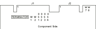
DS1, DS2, DS3, DS4 Drive Select Jumpers
The Drive Select jumper locations are identified as DS1, DS2,
DS3, and DS4. Only one Drive Select jumper is installed on a
drive. The drives are shipped with the jumper installed at DS1.
For every drive in a PC/AT installation, move the jumper from DS1
to DS2 (the special twisted interface cable that is generally
used takes care of assigning a unique address to each drive).
Some other systems may require that each drive be jumpered to a
unique address (i.e., different DS numbers).
RN1 Interface Terminator
The Interface Terminator factory installed at RN1 provides proper
termination for the interface lines. When daisy-chaining multiple
1335 drives, leave the terminator in the last physical drive on
the daisy chain cable; remove the terminator from each of the
other drives. In most PC/AT installations, the C: drive is
actually at the end of the cable and should retain the
terminator.
W1 Write Fault Latch
W1 is the Write Fault Latch. If W1 is present and the drive
encounters a write fault, all writing to the drive is inhibited
until after the drive has been de-selected. If W1 is absent,
fault conditions are not latched. Drives are shipped with a
jumper installed at W1; remove it for PC/AT installations.
W2 is always installed.
W7 is never installed.
W8 is always installed.