Drive Addressing and Interface Termination
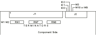
ID0, ID1, ID2 SCSI Address Jumpers
  The SCSI ID (drive address) jumpers are identified as ID0, ID1,
  and ID2. ID selection is binary, as shown in the table below.
|
Jumpers
|
| SCSI Address |
ID2 |
ID1 |
ID0 |
| 0 (default) |
out |
out |
out |
| 1 |
out |
out |
in |
| 2 |
out |
in |
out |
| 3 |
out |
in |
in |
| 4 |
in |
out |
out |
| 5 |
in |
out |
in |
| 6 |
in |
in |
out |
| 7 |
in |
in |
in |
  For  multiple drive installations, on one Host Adapter, each drive must
  have a unique address. Drives are configured as SCSI ID 0 at the factory.

RN1, RN7, RN8 Interface Terminators
  The Interface Terminators factory installed at RN1, RN7, and RN8
  provide proper termination for the interface lines. When
  daisy-chaining multiple drives, leave the terminators installed
  only in the last physical drive on the daisy chain cable; remove
  all three terminators from each of the other drives. In most
  PC/AT installations, the C: drive is actually at the end of the
  cable and should retain the terminators.

W1, W2 Terminator Option
  W1 and W2 select the source of terminator power (+5V) for the
  interface terminators. If a jumper is installed at W1 and no
  jumper is installed at W2 (the factory default configuration),
  the drive provides terminator power. This configuration is used
  for PC/AT applications. If no jumper is installed at W1 but a
  jumper is installed at W2, terminator power is provided by the
  host computer system via interface connector J1, pin 26.

W3 Spindle Option
  W3 selects the spindle control option. If W3 is installed, the
  drive waits for a Start Spindle command (after power is applied)
  to start the spindle motor. If W3 is not installed (the factory
  default configuration), the drive automatically starts the
  spindle motor at power-on. W3 is not installed for PC/AT
  installations.

W18 Bus Parity Option
  W18 selects the parity check option. If W18 is installed, the
  drive neither generates nor detects parity. If W18 is not
  installed (the factory default configuration), the drive
  generates parity and enables parity detection. W18 is not
  installed most PC/AT applications. Refer to your host adapter's
  requirements to verify if parity is to be disabled.

Note: W18 is labeled "W9" on some 137x boards. |
