
Micropolis 1926-15
Hard Disk Drive
Overview
| Model | Capacity | Size | Height | Interface | Bus Type |
|---|---|---|---|---|---|
| Micropolis 1926-15 | 2158MB | 5.25" | FHT | Fast | SCSI2 |
Specifications
| Size | 5-1/4" |
| Interface | SCSI-2F |
| Encoding Method | |
| Formatted Capacity | 2158 MB |
| Disks | 8 |
| Heads | 15 |
| Cylinders | 2772 |
| Sectors | Variable |
| Buffer Size | N/A |
| Average Seek | 13 msec |
| Single Track | 1.4 msec |
| Rotation Speed / Avg. Latency | 5400 rpm +/- 0.5% |
| Transfer Rate to / from media | 10 Mbytes / sec Synchronous |
| Transfer Rate to / from buffer | N/A |
| Tracks Per Inch (TPI) | |
| Bits Per Inch (BPI) | |
| Dimensions | 8.0"L x 5.75"W x 3. 25"H |
| Weight | 5.75 lbs. |
Power Requirements
| +12V +/-5% | +5V +/-5% | Power | |
| Spin up | 4.1A | ||
| Read / Write | 1.0A | 2.1A | |
| Typical | 31 Watts |
Notes
Drive Addressing and Interface Termination
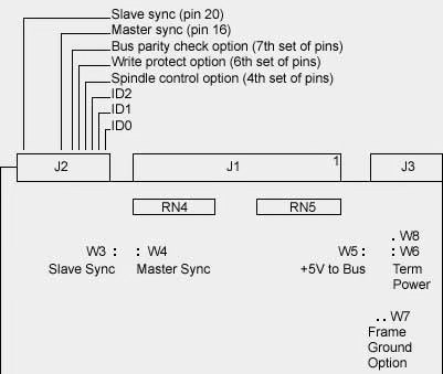
ID0, ID1, ID2 SCSI Address Jumpers The SCSI ID (drive address) jumpers are identified as ID0, ID1, and ID2. ID selection is binary, as shown in the table below.
For multiple drive installations, on one Host Adapter, each drive must have a unique address. Drives are configured as SCSI ID 7 at the factory. RN4 & RN5 Interface Terminators The Interface Terminator factory installed at RN6 provides proper termination for the interface lines. When daisy-chaining multiple drives, leave the terminator installed only in the last physical drive (or drives) on the daisy chain cable; remove the terminator from each of the other drives (or the host computer). Bus Termination Power Option A jumper is installed at W6, at W8, or at W5 to select the source of terminator power (+5V) for the SCSI Bus terminator packs on the device electronics board. When a jumper is installed at W6 (the factory default configuration), the drive provides terminator power to it's on-board terminators. When a jumper is installed at W8 , terminator power is is provided by the host system via the interface cable J1, pin 26 (TERMPWR). When a jumper is installl at both W8 and W5, the drive provides terminator power to its on-board terminators and also to the SCSI bus via interface cable J1, pin 26(TERMPWR). Frame Ground Options Jumper W7 selects the frame ground option. When W7 is installed, the drive's frame is connected to frame ground. When a jumper is not installed at W7 (the factory default configuration), frame ground is not connected to logic ground. Spindle Control Options A jumper bridging pins 7 and 8 of J2 (the 4th set of pins) is used to select the spindle control option. When a jumper is installed, the drive must wait for an interface Start Unit command to start the spindle motor. When a jumper is not installed (the factory default configuration), the drive automatically starts the spindle motor at power-on. Write Protect Option A jumper bridging pins 11 and 12 of J2 (the 6th set of pins) is used to select the write protect option. When a jumper is installed, the drive is write protected. CAUTION: The drive can still be formatted. When a jumper is not installed, (the factory default configuration), the drive is not write protected. Bus Parity Option A jumper bridging pins 13 and 14 of J2(7th set of pins) is used to select the parity check option. When a jumper is not installed, (the factory default configuration), the drive generates parity and enables parity detection. When a jumper is installed, the drive neither generates nor detects parity. Spindle Synchronization Option The Rotational Position Locking field (MODE SELECT command, Page Code 04h) is used to specify spindle synchronization operation; see document #110366 (Scsi Implementation in Micropolis "MZR" Products) and ANSI SCSI Standard. Unsynchronized: If the drive is set to Unsynchronized (PRL=00b), it ignores the SLAVE SYNC signal. Slave: If the drive is set to Slave (RPL=01b), it does not generate the MASTER SYNC signal or the SLAVE SYNC signal but synchronizes its index to the SLAVE SYNC signal (J2,pin 20) supplied by an external source. Master: If the drive is set to MASTER (RPL=10b), it generates the SLAVE SYNC output signal (j2, pin 20) for use directly by the slave drives. Master Control: If the drive is set to Master Control (RPL=11b), it generates the MASTER SYNC signal(j2,pin 20). This output is used by the controller to generate the SLAVE SYNC signal(J2,pin 20) for the slave drives. **** THESE SPECIFICATIONS ARE PRELIMINARY. |
|||||||||||||||||||||||||||||||||||||||