Micropolis 1350-Series
CONFIGURATION INFORMATION
Configuration and Jumper Options
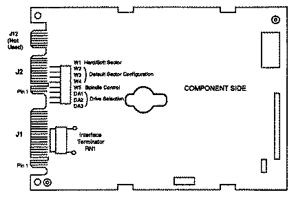
      Drive	  Select Jumpers
     Address	DA3	DA2	DA1

	1	out	out	in
	2	out	in	out
	3	out	in	in
	4	in	out	out
	5	in	out	in
	6	in	in	out
	7 	in	in	in

	"Drive Address 0" (no jumper at DA1, DA2, or DA3)
	 is a "deselect" (i.e., no drive selected).
For many multiple drive installation, each drive must have a unique address. An exception is that for every drive in a PC/AT installation, verify that the only Drive Address jumper is at DA2; move the jumper if necessary (the special twisted interface cable that is generally used takes care of adding a unique address to each drive). PC/AT controllers can typically support a maximum of two drives. Interface Termination The Interface Terminator factory installed at RN1 provides proper termination for the interfacelines. When daisy-chaining multiple drives, leave the terminator installed only in the last physical drive on the daisy-chain cable; remove the terminator from each of the other drives. In most PC/AT applications, the C: drive is actually at the end of the cable and should retain the terminator
Spindle Control W5 controls the spindle option. If W5 is installed, the drive waits for a Start Spindle command (after power is applied) to start the spindle motor. If W5 is not installed (the factory default configuration), the drive automatically starts the spindle motor at power-on. W5 is not installed for PC/AT applications.
Sectoring W1 selects the sectoring mode. If W1 is installed, the drive operates in the soft-sectored mode. If W1 is not installed (the factory default configuration), the drive operates in the the hard-sectored mode. W1 is not installed for PC/AT applications. The number of bytes per sector may be specified using the Set Bytes Per Sector command or by selecting a default sector configuration with jumpers W2, W3, and W4 as follows:
    Jumpers		Sectors			Bytes/Sector
W4	W3	W2			Formatted	Unformatted
out	out	out	   35		512		595
out	out	in	   36		512		578 *
out	in	out	   19		1024		1096
out	in	in	    9		2048		2314
in	out	out	    5		4096		4166
in	out	in	   32		512		651
in	in	out	   64		256		325
in	in	in	    1		20,832		20,832

* This is the default (factory installed) configuration,
  and is recommended for PC/AT applications.