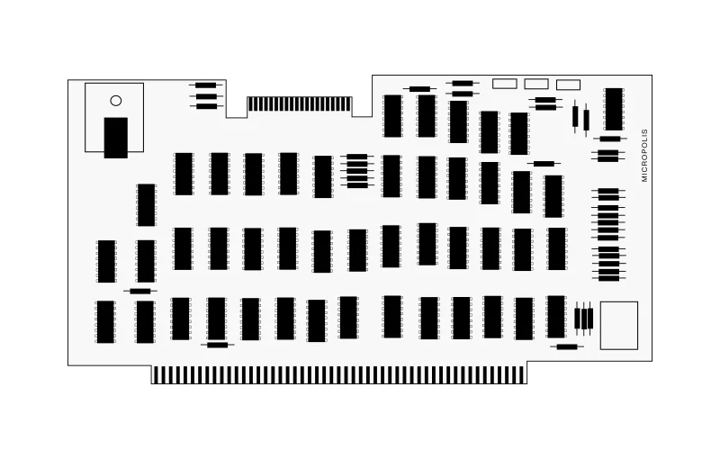
Micropolis 1071
Controller Board
Overview
| Model | Capacity | Size | Height | Media Type |
|---|---|---|---|---|
| Micropolis 1071 | - | - |
This MFM or GCR encoding controller is a single printed circuit board,
physically and electrically compatible with S-100 bus and
8080/Z80 microcomputers. In MFM it utilizes 16 sectors and 256
data bytes per track and will operate at either 2 or 4 MHz. The 1071 controller
is sometimes named 1071-1 in documentation.
Height (not including the edge connector to the motherboard):
Height: 5.0" or 12.7 cm
Width: 10.0" or 25.4 cm
The edge connector for the interface cable is recessed to keep the overall height at 5.0" when the cable is connected.
Data is recorded on the disk in concentric tracks. The outermost track is track zero. Each track is divided into 16 sectors. The beginning of each sector is indicated by a sector hole punched in the disk. An index hole is located halfway between the holes for sector 15 and sector zero. The sector and the index hole are sensed by a photo transistor in the disk drive. Each disk sector consists of a preamble, sync byte, header, data, 4 checksum, and a postamble. Each of these fields are described below.
Preamble
The preamble is composed of approximately 40 bytes of zero (0) data bits. The preamble is automatically generated by the disk controller and is necessary to provide tolerance for the mechanical alignment and electrical characteristics of the sector/index sensor. It also provides a field of known data pattern for synchronization of the read data decoder.
Sync Byte
The sync byte is a byte of data (FFH) which is used in the disk controller to define the beginning of useful data.
Header
The header is a 2-byte block consisting of the binary track address of the track on which the sector resides (0-76 (34)) and the address of the sector (0-15). The header is used to verify that the proper sector is being accessed in a disk I/O operation.
Data
The data field consists of 266 bytes of user data. More exactly, the data field per sector is 256 Bytes of actual payload plus 10 Bytes of dummy padding.
Checksum
The checksum is a one byte error detection code that provides error detection in read operations. The checksum is computed by the CPU as follows:
a) The accumulator and carry are initially cleared;
b) Each byte of the header and data fields is added to the accumulator with carry.
In write operations, the computed checksum is written immediately following the data field.. In read cperations, the checksum is recomputed fram. the read data and is compared with the checksum byte which is read. If they do not compare, a read error has occurred.
Postamble
The rest of the sector from the checksum to the next sector hole is filled with zero data bits. The length of the postamble allows for the mechanical tolerance in the placement of sector holes on the disk and tolerance for disk speed and write clock variations.
Height (not including the edge connector to the motherboard):
Height: 5.0" or 12.7 cm
Width: 10.0" or 25.4 cm
The edge connector for the interface cable is recessed to keep the overall height at 5.0" when the cable is connected.
Disk Data Format
The Micropolis 1071 is a hard-sectored media disk controller and related successor of the PCB-only Micropolis 100085-01-8A floppy-disk drive controller board.Data is recorded on the disk in concentric tracks. The outermost track is track zero. Each track is divided into 16 sectors. The beginning of each sector is indicated by a sector hole punched in the disk. An index hole is located halfway between the holes for sector 15 and sector zero. The sector and the index hole are sensed by a photo transistor in the disk drive. Each disk sector consists of a preamble, sync byte, header, data, 4 checksum, and a postamble. Each of these fields are described below.
Preamble
The preamble is composed of approximately 40 bytes of zero (0) data bits. The preamble is automatically generated by the disk controller and is necessary to provide tolerance for the mechanical alignment and electrical characteristics of the sector/index sensor. It also provides a field of known data pattern for synchronization of the read data decoder.
Sync Byte
The sync byte is a byte of data (FFH) which is used in the disk controller to define the beginning of useful data.
Header
The header is a 2-byte block consisting of the binary track address of the track on which the sector resides (0-76 (34)) and the address of the sector (0-15). The header is used to verify that the proper sector is being accessed in a disk I/O operation.
Data
The data field consists of 266 bytes of user data. More exactly, the data field per sector is 256 Bytes of actual payload plus 10 Bytes of dummy padding.
Checksum
The checksum is a one byte error detection code that provides error detection in read operations. The checksum is computed by the CPU as follows:
a) The accumulator and carry are initially cleared;
b) Each byte of the header and data fields is added to the accumulator with carry.
In write operations, the computed checksum is written immediately following the data field.. In read cperations, the checksum is recomputed fram. the read data and is compared with the checksum byte which is read. If they do not compare, a read error has occurred.
Postamble
The rest of the sector from the checksum to the next sector hole is filled with zero data bits. The length of the postamble allows for the mechanical tolerance in the placement of sector holes on the disk and tolerance for disk speed and write clock variations.