
Micropolis 1654-7
Hard Disk Drive
Overview
| Model | Capacity | Size | Height | Interface | Bus Type |
|---|---|---|---|---|---|
| Micropolis 1654-7 | 161MB | 5.25" | HHT | ESDI |
Specifications
| Size | 5-1/4" |
| Interface | ESDI |
| Encoding Method | |
| Formatted Capacity | 161.0 MB |
| Disks | 4 |
| Heads | 7 |
| Cylinders | 1249 |
| Sectors | 36 |
| Buffer Size | N/A |
| Average Seek | 16 msec |
| Single Track | 4 msec |
| Rotation Speed / Avg. Latency | 3600 rpm +/- 0.5% |
| Transfer Rate to / from media | 10 Mbits/sec |
| Transfer Rate to / from buffer | N/A |
| Tracks Per Inch (TPI) | |
| Bits Per Inch (BPI) | |
| Dimensions | 8.0"L x 5.75"W x 1.625"H |
| Weight | 5.75 lbs. |
Power Requirements
| +12V +/-5% | +5V +/-5% | Power | |
| Spin up | 2.0A (max) | ||
| Read / Write | .7A avg | .9A avg | |
| Typical | 14 Watts |
Notes
Drive Addressing and Interface Termination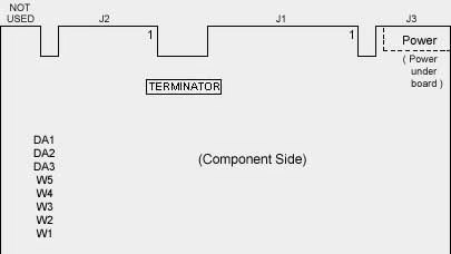
RN1 Interface Terminator The Interface Terminator factory installed at RN1 will provide proper termination for the interface lines. When daisy-chaining multiple drives, leave the terminator installed only in the last physical drive on the daisy chain; remove the terminator from each of the other drives. In most PC/AT installations, the C: drive is actually at the end of the cable and should retain the terminator. DA1, DA2, DA3 Drive Address Jumpers The drive address jumpers are identified as DA1, DA2 and DA3. Address selection is binary, as shown in the table below. The ESDI controller's documentation will specify the drive address to use.
"Drive address 0" (no jumper at DA1, DA2, or DA3) is a "deselect" (i.e., no drive selected). Drives are factory configured as Drive Address 1. For many multiple drive installations, each drive must have a unique address. An exception is that for every drive in a PC/AT installation, verify that only Drive Address is at DA2; move the jumper if necessary (the special twisted interface cable that is generally used takes care of assigning a unique address to each drive). PC/AT controller can typically support a maximum of two drives. W5 Selects the Spindle Control Option. W5 selects the spindle a control option. If W5 is installed, the drive waits for a Start Spindle command (after power is applied) to start the spindle motor. If W5 is not installed (the factory default configuration), the drive automatically starts the spindle motor at power-on. W5 is not installed for PC/AT applications. W1 Selects the Sectoring Mode. If W1 is installed, the drive operates in the soft-sectored mode. If W1 is not installed (the factory default configuration), the drive operates in the hard-sector mode. W1 is not installed for most PC/AT in applications. W2, W3, W4 Sector Size Option The number of bytes per sector may be specified using the Set Bytes Per Sector command or by selecting a default sector configuration with jumpers W2, W3, and W4 as follows:
* This is the default (factory installed) configuration and is recommended for PC/AT applications | |||||||||||||||||||||||||||||||||||||||||||||||||||||||||||||||||||||||||||||||||||||||||||||||