
Micropolis 1674-6
Hard Disk Drive
Overview
| Model | Capacity | Size | Height | Interface | Bus Type |
|---|---|---|---|---|---|
| Micropolis 1674-6 | 136MB | 5.25" | HHT | SE | SCSI1 |
Specifications
| Size | 5-1/4" |
| Interface | SCSI |
| Encoding Method | RLL |
| Formatted Capacity | 135.5 MB |
| Disks | 4 |
| Heads | 6 |
| Cylinders | 1249 |
| Sectors | 36 |
| Buffer Size | N/A |
| Average Seek | 16 msec |
| Single Track | 4 msec |
| Rotation Speed / Avg. Latency | 3600 rpm +/- 0.5% |
| Transfer Rate to / from media | 10 Mbits / sec |
| Transfer Rate to / from buffer | N/A |
| Tracks Per Inch (TPI) | |
| Bits Per Inch (BPI) | |
| Dimensions | 8.0"L x 5.75"W x 1.625"H |
| Weight | 5.75 lbs. |
Power Requirements
| +12V +/-5% | +5V +/-5% | Power | |
| Spin up | 2.0A (max) | ||
| Read / Write | .7A avg | .9A avg | |
| Typical | 15 Watts |
Notes
Drive Addressing and Interface Termination
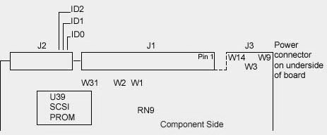
ID0, ID1, ID2 SCSI Address Jumpers The SCSI ID (drive address) jumpers are identified as ID0, ID1, and ID2. ID selection is binary, as shown in the table below.
For multiple drive installations, on one Host Adapter, each drive must have a unique address. Drives are configured as SCSI ID 0 at the factory. RN9 Interface Terminator The Interface Terminator factory installed at RN9 provides proper termination for the interface lines. When daisy-chaining multiple drives, leave the terminator installed only in the last physical drive (or drives) on the daisy chain cable; remove the terminator from each of the other drives (or the host computer). W1, W2 Terminator Option W1 and W2 select the source of terminator power (+5V) for the interface terminator. If a jumper is installed at W1 and no jumper is installed at W2 (the factory default configuration), the drive provides terminator power. This configuration is used for PC/AT applications. If no jumper is installed at W1 but a jumper is installed at W2, terminator power must provided by the host computer system via interface connector J1, pin 26. W3, Spindle Option W3 selects the spindle control option. If W3 is installed, the drive waits for a Start Spindle command after power is applied to start the spindle motor. If W3 is not installed (the factory default configuration), the drive automatically starts the spindle motor at power-on. W3 is not installed for PC/AT installations. W9 Bus Parity Option W9 selects the parity check option. If W9 is installed, the drive neither generates nor detects parity. If W9 is not installed (the factory default configuration), the drive generates parity and enables parity detection. W9 is usually not installed for PC/AT applications. Verify the correct configuration required by your Host Adapter. |
|||||||||||||||||||||||||||||||||||||||